
M.V. Soft Rocker
 M.V. Soft Rocker | Designing the Boat |
| | Back to Search Page | |
| After years of boating we had many requirements for a new boat. The design mantra became "warm, dry and economical" with a comercial hull. The basic design for converting a commercial fish boat came from a vessel named Merganser that we saw in Ladysmith Harbour. |
|
Merganser |
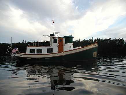
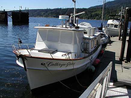
| Below are more boats that influenced the final design of Soft Rocker |
|
Nordic Tugs, like this one, had the basic design we were looking for with the wheel house over the engine, berths forward and living area aft. The trunk cabin is a little too high for our taste. The lines of the windows are poor and there is no need for the elaborate hatch over the aft cabin entrance. |
This vintage raised deck cruiser has the same basic layout as we were interested in. |
 |
 |
|
|
| | Top of Page | |
| Designed and built by Lou Zink |
Bill Garden design |
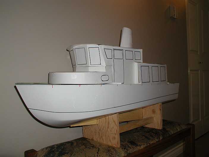 |
| Ultimately we built a Model |
|
We settled on a Barry Ferrell hull, prepared it for construction and then
started designing the boat. (Further information about finding and preparing the hull can be
found on the (Search Page) With a pneumatic stapler and a few hundred feet of fir lath the next step
was to build a full-sized replica of the interior of the boat - (poor man's
CAD). The object was to establish some of the spatial relationships, head room,
berth sizes and begin to develop the lines of the exterior of the boat. It took three days, but the process served the purpose and provided
invaluable measurements that would be used for installing bulkheads and
establishing floor levels. Pictures provided future |
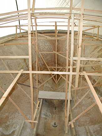 | |
| Looking forward these are the bunks in the forward cabin (upper on the starboard side lower on the port side) Mocking this up allowed us to make good use of the flare in the bow for the upper bunk. It also showed where the bulkheads would go at the head of each bunk. Having bulkheads that are"square" to the bunk makes the beds more comfortable when you sit up to read. | The two pieces of lath on either side of this picture are showing where the wheelhouse floor will be built above the engine room pieces of lath on either side of this picture are showing where the wheelhouse floor will be built above the engine room |
| Looking aft is a representation of the rear wall of the aft cabin. In the foreground is a mock up of one of the bulkheads which will support the sole | Looking forward, from the aft cabin - the highest structure is the wheelhouse roof. |
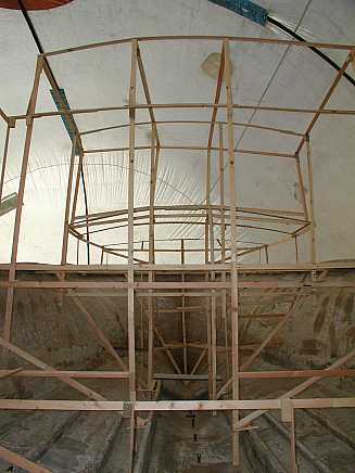 | |
| Look hard and you can see the aft cabin sole, then the wheelhouse floor with the forward cabin and bunks in front of the wheelhouse. | Looking forward through the aft cabin......the stick on the left, running fore and aft denotes the aft cabin sole (floor) |
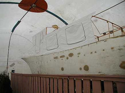 | |
With some paper and a glue gun I was able to get an idea of what the lines would look like and where the windows would be placed. | These pictures were enlarged and pencil drawings made on top of them to get better lines and proportions. |
| I took lots of pictures of each bulkhead, walls, berths etc and then penciled in measurements on the pictures before taking down the wood mock up. The measurements were useful for material calculations and further design work |
| After these "mock ups" were photographed, drawings were made on "flip chart" paper (one inch squares). A basic drawing without details was made first then photo copies where made. The copies were used to add details and make modifications. As work progressed the drawings and designs were modified and revised |
| This process was inexpensive and better than using a Computer Assisted Design (CAD) program because you literally could see what the result would be. The lath sticks also facilitated lots of discussions with fellow boaters and other builders. Some of the "discussions" could get a little heated but the end results allowed for plenty of input and the percolation of innovative ideas. |
| | Top of Page | |