| |
Diesel Hot Water Heater |
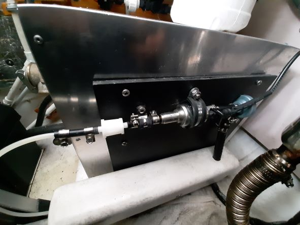
Soft Rocker is heated by a
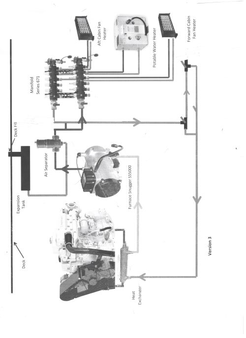
hydronic heating system. (Hydronics is the use of a liquid heat-transfer medium in heating systems. The working fluid is 50% glycol and 50%
water.)
The primary heat source for this fluid is the diesel water
heater located to the left, and available from DK Smith International. The
heater comes in kits or individual parts.
This model is a 5KW 12VDC Diesel Heater (Kit), SKU # (Stock
Keeping Unit Number) PHP -50WA7.
This heater is also distributed under the brand name “Snugger”
Model #SS5000. Search - snugger heater servicing and Technical
Support is available from John Reimer 416-616-9440
Use Back Arrow To Return To This Page From This Link
|
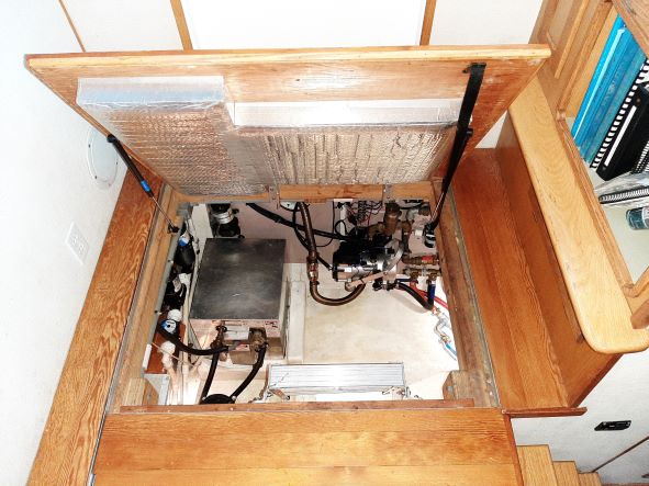
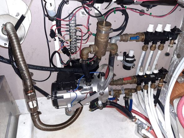
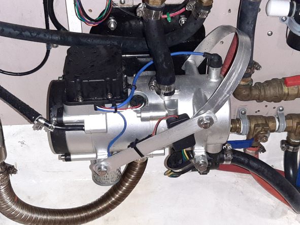 | Heater installed on port side of the engine room |
| 
|
 |  |
|
A secondary
source of heat comes from the boat’s main engine.
The engine heat
is transferred to the heating system’s fluid by a heat exchanger. Heated engine
coolant is passed through one passage in the yellow heat exchanger at
one end and then back to the engine through the other end. The heating
system fluid is passed through another passage in the yellow heat exchanger.
The heat is then “exchanged”
from the engine to the heating system.
Heat from the
engine or the Diesel Hot Water Heater (or both sources) can then be used to
heat Soft Rocker.
There is a sacrificial
zinc on the left end of the heat exchanger that should be checked and replaced
when needed.
Heat exchangers
are commonly available from engine suppliers.
|
|
Engine Heat Exchanger
| |
Distribution Manifold Note: This is a 6 zone manifold, the one used in Soft Rocker
is a 3 zone model of the same design and manufacture. |
The heated
fluid is delivered to 3 zones (2 cabin heaters and 1 potable hot water tank)
from the manifold shown on the left.
Each of
the three circuits have a “supply” and “return” line from the cabin heaters and
the potable hot water tank. The “supply” lines have zone valves (white caps -
top of the manifold) which will “cut off” or reduce the flow to a circuit.
The return
lines have valves and flow indicators (white caps - bottom of the manifold). These valves
are used to balance the flow between Zones. The
disk in the flow indicators will rise and fall indicating the pressure
in the system; the movement of this disk also indicates that
fluid is moving in the system. If there is no idication of fluid flow
turn the system off and investigate'
This manifold is made by Caleffi, the
model is a 671 series manifold (search using caleffi manifold 671). Manifolds
like this one, are available from plumbing wholesalers (especially hydronic
heating suppliers).
|
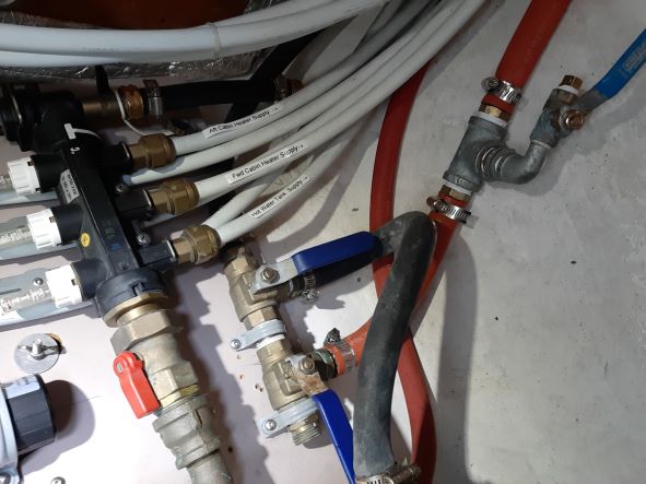 | Distribution manifold as installed in
the forward port side of the engine room |
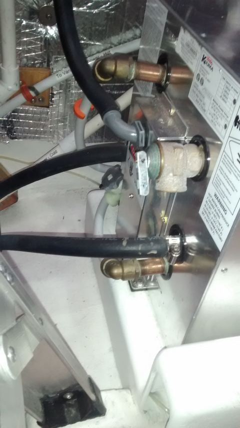
| Hot water tank as installed in
the aft port side of the engine room |
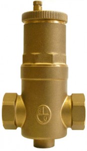 The heating
system fluid is passed through another passage in the yellow heat exchanger.
Bell & Gossett Model EASB – JR Air
Separator
|
A hydronic heating system must rid
itself of any air to perform efficiently. When the system is built (or when a
major alteration is made) it should be “bleed” of all air.
To keep air from accumulating while the
system is being used, a permanent separator should be used to remove air
bubbles from the circulating fluid. Below is a quote from the Caleffi Website
that describes the purpose of a separator.
“An air separator is a multi-pass
device and over time it will "scrub out" air and can bring the
dissolved air content down to less than 0.5% of system volume. In that
condition, the water will provide) excellent heat transfer (air is an insulator,
not a good conductor), and virtually eliminate noise (air makes noise in a
hydronic system).
Removing air also reduces corrosion in the system.”
Manual |
| |
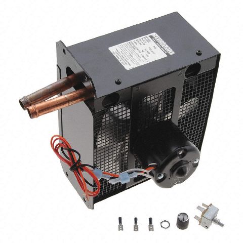
| In the three hydronic circuits (or zones) there are two bus heaters like this one and the potable hot water tank. |
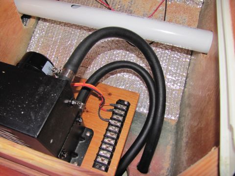 | .
|
| This is the bus heater in the forward cabin |
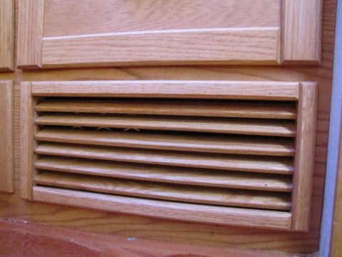
The forward cabin bus heater is located behind this grill
|
 | |
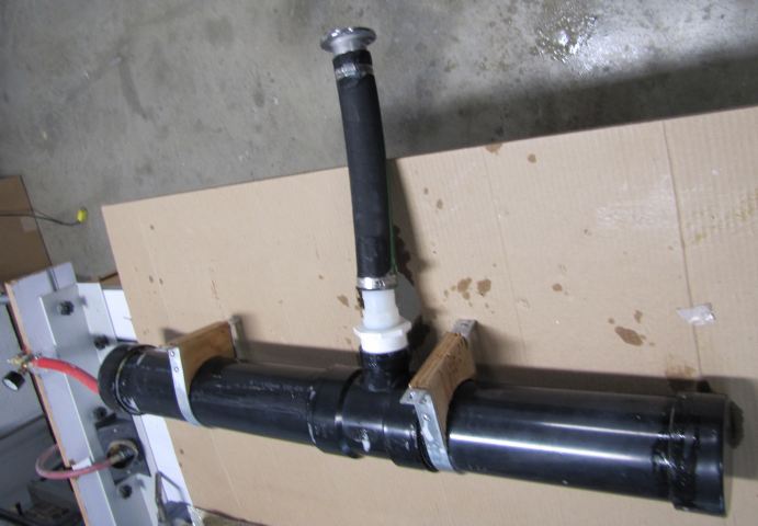 | Heating system header tank located under the port side deck. The deck filler inlet is at the top of the image.
|
| |


